"Graphic" tab
Applies to: viflow (subscription | 9 | 8) | Article: 1561978 | Updated on 26.04.2024
In this register you will find all the important tools for editing and adjusting graphics and drawing elements.

"Font" group
The functions related to the text, such as font, font size, alignment, color, are summarized in this group.

If objects with text or individual text passages are marked on the graphic, the text properties can be changed here. Choose the font, size, color, and other attributes, such as bold, italic, or underline.
You can access detailed text settings by clicking on the arrow symbol [  ] at the bottom right of the group.
Paragraph Group
The text-related features, such as paragraph and alignment, are grouped together in this group.

If objects with text or individual text passages are marked on the graphic, you specify the horizontal and vertical text alignment here.
You can access detailed text settings by clicking on the arrow symbol [ .png) ] at the bottom right of the group.
] at the bottom right of the group.
Tools Group
Important tools for modeling, such as the connector, drawing elements or the pointer tool, are combined in this group.

button/option |
function |
a notice |
|
If other functions were previously active (e.g. connector ), the basic setting can be called up by clicking on the pointer . |
For other choices, click the arrow icon [ |
|
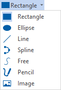
If you click Text , you can draw a text box on the drawing sheet and enter text with a mouse click. |
Not suitable for editing viflow objects, see note below. |
|
To insert a new Visio drawing object, open the selection menu [ |
Once selected, click on the drawing sheet to create an object of that shape. |
|
For adding new connection points for the connector, eg on a process shape. |
With Move Connector Point turned on, CTRL-click the shapes. |
|
Enabled via the function [ |
|
|
If the connector is active, Visio and viflow objects can be connected to each other in the graphic. |
Information about the creation and modeling of information can be found under ››› Modeling information graphics. |
|
If several shapes are marked in the graphic, they can be connected with one click. |
Shape group
Other tools for formatting Visio shapes are grouped together in this group.

To fill
Specify the fill color and other fill options for an object ("shape") previously selected on the drawing sheet by opening the Fill drop-down menu.
line
Specify the line color and other line options for an object ("shape") previously marked on the drawing sheet by opening the Line drop-down menu.
The shade
Set the shadow color and other shadow options for an object ("shape") previously selected on the drawing sheet by opening the Shadow drop-down menu.
Arrange group
Other tools for arranging and placing graphic objects are combined in this group.

Position
You will find various options for positioning and aligning drawing objects (e.g. right- justified or left -justified) after opening the Position drop-down menu.
Forward / Backward
If several drawing objects are on top of each other, you can specify which element should be placed in the foreground or background by opening these selection menus.
Group
If several drawing objects have been selected on the drawing sheet, they can be combined in a group using Group or individual objects can be added to a group. A mouse click is then sufficient to mark the entire group with all elements, for example to move or copy them.
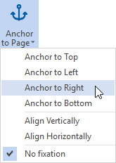
Fix
If the drawing sheet size is changed, you can specify how certain drawing objects or shapes should behave. If you use your own graphic template with a company logo for your processes, you can fix this, for example, at the top right with the same edge spacing.


.png)
 ] of the Pointer button. You can find more information on this in the chapter
.png)

.png)


